
NEMA 14 35 MM Stepper Lead Screw Linear Actuator
The NEMA 14 stepper lead screw linear actuator is a 35 mm linear actuator widely used for precise linear movement applications.
This size 14 actuator provides up to 230 N of continuous thrust and is available in External, Non-Captive, Captive, and Kaptive configurations.
.png)
Motor Characteristics
Swipe left or right to view the full table.
| Motor | Voltage [V] | Current [A RMS] | Resistance [Ω] | Inductance [mH] | Weight [g] | Lead Wire No. | Motor Length mm (Dimension 'L') |
|---|---|---|---|---|---|---|---|
| 14-2105 | 6.6 | 0.5 | 13.2 | 14 | 189 | 4 | 33.6 |
| 14-2110 | 3.5 | 1 | 3.5 | 3.6 | 189 | 4 | 33.6 |
| 14-2115 | 2.7 | 1.5 | 1.8 | 1.9 | 189 | 4 | 33.6 |
| 14-2205 | 12 | 0.5 | 24 | 29 | 210 | 4 | 45.6 |
| 14-2210 | 6 | 1 | 6 | 7.2 | 210 | 4 | 45.6 |
| 14-2215 | 4 | 1.5 | 2.7 | 3.2 | 210 | 4 | 45.6 |
Note: Motor insulation class B. Motor temperature rise 80°C. Ambient temperature -20°C to 55°C.
Available Lead Screw and Travel per Step
Swipe left or right to view the full table.
| Screw Dia. [inch] | Screw Dia. [mm] | Lead [inch] | Lead [mm] | Lead Code | Travel Per Step @ 1.8° [mm]* | Travel Per Step @ 0.9° [mm]* |
|---|---|---|---|---|---|---|
| 0.25 | 6.35 | 0.024 | 0.6096 | AA | 0.003 | 0.0015 |
| 0.25 | 6.35 | 0.025 | 0.635 | A | 0.0032 | 0.0016 |
| 0.25 | 6.35 | 0.048 | 1.2192 | B | 0.0061 | 0.003 |
| 0.25 | 6.35 | 0.05 | 1.27 | D | 0.0064 | 0.0032 |
| 0.25 | 6.35 | 0.0625 | 1.5875 | F | 0.0079 | 0.004 |
| 0.25 | 6.35 | 0.096 | 2.4384 | J | 0.0122 | 0.0061 |
| 0.25 | 6.35 | 0.1 | 2.54 | K | 0.0127 | 0.0064 |
| 0.25 | 6.35 | 0.125 | 3.175 | L | 0.0159 | 0.0079 |
| 0.25 | 6.35 | 0.192 | 4.8768 | Q | 0.0244 | 0.0122 |
| 0.25 | 6.35 | 0.2 | 5.08 | R | 0.0254 | 0.0127 |
| 0.25 | 6.35 | 0.25 | 6.35 | S | 0.0318 | 0.0159 |
| 0.25 | 6.35 | 0.3333 | 8.4667 | U | 0.0423 | 0.0212 |
| 0.25 | 6.35 | 0.384 | 9.7536 | W | 0.0488 | 0.0244 |
| 0.25 | 6.35 | 0.5 | 12.7 | Y | 0.0635 | 0.0318 |
| 0.25 | 6.35 | 1 | 25.4 | Z | 0.127 | 0.0635 |
| 0.236 / 0.25 / 0.315 | 6 / 6.35 / 8 | 0.0394 | 1 | AB | 0.005 | 0.0025 |
| 0.25 / 0.315 | 6.35 / 8 | 0.0787 | 2 | G | 0.01 | 0.005 |
| 0.315 | 8 | 0.1575 | 4 | M | 0.02 | 0.01 |
| 0.315 | 8 | 0.315 | 8 | T | 0.04 | 0.02 |
| 0.236 / 0.315 | 6 / 8 | 0.1969 | 5 | E | 0.025 | 0.0125 |
| 0.315 | 8 | 0.3937 | 10 | C | 0.05 | 0.025 |
| 0.25 | 6.35 | 0.0313 | 0.794 | N | 0.004 | 0.002 |
* Motor wiring and screw lead can be customized upon request.
* 9.525 mm diameter screw can be applied in External Type.
* Values truncated.
Dimensional Drawings

External dimensional drawing. Click to enlarge.

Non-captive dimensional drawing. Click to enlarge.

Captive dimensional drawing. Click to enlarge.

Kaptive dimensional drawing. Click to enlarge.
Speed Thrust Curves

Single stack speed thrust curve. Click to enlarge.

Double stack speed thrust curve. Click to enlarge.
Test condition: Testing voltage 24 VDC. Driver model DS-OLS2-FPD bipolar chopper driver at rated current RMS. Motor thrust changes with different voltage and driver selections. A 50% thrust margin is recommended.
Available Options

EK1 encoder photo. Click to enlarge.

EK1 encoder drawing. Click to enlarge.
| Resolution CPR | 100 | 108 | 120 | 125 | 128 | 200 | 250 | 256 | 300 | 360 | 400 | 500 | 1000 | 512 | 720 | 800 |
|---|---|---|---|---|---|---|---|---|---|---|---|---|---|---|---|---|
| Single Ended Output | 0 | 1 | 2 | 3 | 4 | 5 | 6 | 7 | 8 | 9 | 10 | 11 | 12 | 13 | 14 | 15 |
| Differential Output | A | B | C | D | E | F | G | H | I | J | K | L | M | N | O | P |
Note: EK1 encoder is only available for NEMA 14 External and Captive linear actuator configurations.

EK2 encoder photo. Click to enlarge.

EK2 encoder drawing. Click to enlarge.
| Resolution CPR | 50 | 100 | 192 | 200 | 250 | 256 | 360 | 400 | 500 | 720 | 900 | 1000 | 1250 | 2000 | 2500 | 4000 | 5000 |
|---|---|---|---|---|---|---|---|---|---|---|---|---|---|---|---|---|---|
| Single Ended Output | 0 | 1 | 2 | 3 | 4 | 5 | 6 | 7 | 8 | 9 | 10 | 11 | 12 | ||||
| Differential Output | A | B | C | D | E | F | G | H | I | J | K | L | M | N | O | P | Q |

Teflon Coating
If your application requires a greaseless screw and nut combination, DINGS’ offers Teflon coated lead screws for stepper linear actuators.
Teflon coated lead screws can improve life cycle and thrust force generation compared with conventional SUS lead screws.
Teflon coating can be applied across the full range of lead screw options and actuator types including External, Non-Captive, Captive, and Kaptive. Anti-backlash nuts can also be combined with Teflon coated lead screws.

External anti-backlash nut. Click to enlarge.

Non-captive anti-backlash nut. Click to enlarge.
Anti-Backlash Nuts
External and non-captive anti-backlash nut options are available depending on actuator configuration and lead screw selection.
According to the selected screw lead code, the length of the anti-backlash nut can change.

| Rated Voltage | DC 24V ± 5% |
|---|---|
| Resistance | 217Ω ± 10% |
| Power | 4W |
| Hold Torque | >0.3 N·m |
| Insulation | B |
| Insulation Resistance | >100MΩ DC500V |
| Dielectric Strength | AC 1000V for 1 sec |
| Retraction Time | 50 ms |
| Release Time | 50 ms |
| Gyration Gap | 1° |
| Emergency Brake Cycle | 200 cycles |
| Lifetime | 500,000 cycles |
| Noise Level | <60 dB |

Brake dimensional drawing. Click to enlarge.
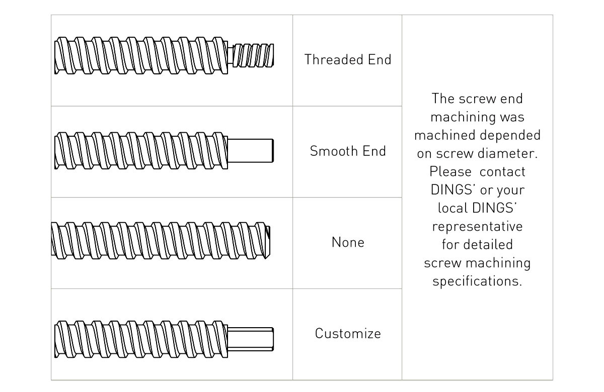
Screw end machining. Click to enlarge.
Customization Options
DINGS’ Motion USA customizes Stepper Linear Actuators, PM Stepper Linear Actuators, Slide Actuators, and Voice Coil Motors for OEM applications.
Motor Platform
NEMA size, stack size, motor type, stepper or BLDC motor options, voltage and current ratings, windings, insulation class, force, torque, and speed.
Linear Motion Design
Stroke length, lead screw selection, shaft configurations, end machining, lubrication on lead screw, and actuator style.
Electrical Integration
Cabling, connectors, lead wire details, harness routing, winding adjustments, and electrical requirements for the application.
Environmental Requirements
Coatings, IP ratings, clean room capabilities, lubrication requirements, and application-specific material or protection needs.
Resources
Downloads
Part Number Construction
1. Motor Size
14 = NEMA 14 / 35 mm frame size.
2. Linear Actuator Type
E = External, N = Non-Captive, C = Captive Cylinder, K = Kaptive.
3. Motor Step Angle
2 = 2-phase 1.8°, 4 = 2-phase 0.9°, 5 = 5-phase 0.72°.
4. Motor Length
1 = Single stack, 2 = Double stack, 3 = Triple stack.
5. Rated Current / Phase
XX = X.X A / phase.
6. Lead Screw Code
Select the code from the lead screw code table.
7. Lead Wire Number
4 = 4-wire, 6 = 6-wire, 8 = 8-wire leads.
8. Lead Screw Length / Stroke
External / Non-Captive: XXX = screw length. Captive / Kaptive: XXX = stroke.
9. Lead Screw Surface Treatment
T = Teflon coating, S = Standard, K = Electrophoretic Teflon, C = Custom.
10. End Machining
M = Metric, U = UNC, S = Smooth, C = Custom, N = None.
11. Nut Style
S = Standard flange nut, A = Anti-backlash nut, C = Customization.
12. Option
EKX = Encoder, P = Manual knob, B = Brake, X = Rear shaft, R = Encoder ready, C = Custom, N = None.
13. Customer Sequence Number
Customer or project-specific sequence number.
Need help selecting or customizing a NEMA 14 linear actuator?
DINGS’ Motion USA can help review thrust, speed, lead screw selection, stroke, actuator type, wiring, connector, lubrication, brake, encoder, and clean room requirements for your application.