
NEMA 8 DLM 20 MM Slide Actuator
The NEMA 8 DLM and L·R DLM slide actuator family is a compact 20 mm linear module that combines a stepper motor, lead screw, and guided carriage into a ready-to-integrate motion solution.
Designed for OEM systems, the 20 mm DLM platform offers flexible lead screw options, multiple stroke selections, and left/right mounting configurations for precise guided linear motion.
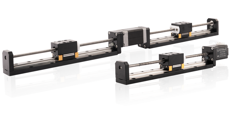
NEMA 8 DLM / L·R DLM Overview
The DLM and L·R DLM 20 mm series provides a compact linear module platform for applications that need guided motion in a small mechanical envelope. The DLM configuration is a standard compact linear module, while the L·R DLM version supports left/right layout requirements for applications where mounting orientation, cable routing, or installation footprint matters.
Compact Travel
Stroke options from 20 mm to 200 mm support small automated positioning systems.
Lead Screw Driven
Multiple lead codes help balance speed, thrust, and resolution requirements.
DLM / L·R DLM
Choose standard DLM or left/right L·R DLM layout based on integration needs.
OEM Ready
Configurable stroke, wiring, lead screw, and application-specific options are available.
Motor Characteristics
Swipe left or right to view the full table.
| Motor | Voltage [V] | Current [A RMS] | Resistance [Ω] | Inductance [mH] | Motor Length mm (Dimension 'L') | Lead Wire No. |
|---|---|---|---|---|---|---|
| 8E2105 | 2.5 | 0.5 | 5.1 | 1.5 | 27.2 | 4 |
| 8E2205 | 4.4 | 0.5 | 8.8 | 2.7 | 38.1 | 4 |
Available Lead Screw and Travel Per Step
Swipe left or right to view the full table.
| Screw Dia. [inch] | Screw Dia. [mm] | Lead [inch] | Lead [mm] | Lead Code | Travel Per Step @ 1.8° [mm] |
|---|---|---|---|---|---|
| 0.138 | 3.5 | 0.0118 | 0.3 | AF | 0.0015 |
| 0.138 | 3.5 | 0.024 | 0.6096 | AA | 0.003048 |
| 0.128 | 3.24 | 0.0394 | 1 | AB | 0.005 |
| 0.138 | 3.5 | 0.048 | 1.2192 | B | 0.006096 |
| 0.138 | 3.5 | 0.0787 | 2 | G* | 0.01 |
| 0.138 | 3.5 | 0.096 | 2.4384 | J | 0.012192 |
| 0.138 | 3.5 | 0.1575 | 4 | M | 0.02 |
| 0.138 | 3.5 | 0.315 | 8 | T | 0.04 |
* Lead code G is only available for L·R DLM 20 mm.
Mechanical Specifications
Swipe left or right to view the full table.
| Model | C100B Dynamic [N] | Co Static [N] | Mro [Nm] | Mpo [Nm] | Myo [Nm] |
|---|---|---|---|---|---|
| DLM / L·R DLM20 | 714 | 1071 | 3.794 | 2.219 | 2.219 |
Dimensional Drawings


Available Stroke Selection
Swipe left or right to view the full table.
| Size A [mm] | Stroke B [mm] | Single Stack Weight [kg] | Double Stack Weight [kg] |
|---|---|---|---|
| 60 | 20 | 0.124 | 0.147 |
| 80 | 40 | 0.134 | 0.157 |
| 100 | 60 | 0.144 | 0.167 |
| 120 | 80 | 0.155 | 0.177 |
| 140 | 100 | 0.166 | 0.189 |
| 190 | 150 | 0.192 | 0.215 |
| 240 | 200 | 0.217 | 0.240 |
* Weight values are for reference only and may vary with actual configuration.
Swipe left or right to view the full table.
| Stroke [mm] | Single Stack | Double Stack | ||
|---|---|---|---|---|
| Total Length [mm] | Weight [kg] | Total Length [mm] | Weight [kg] | |
| 20 | 161.2 | 0.154 | 172.1 | 0.177 |
| 40 | 201.2 | 0.174 | 212.1 | 0.197 |
| 60 | 241.2 | 0.194 | 252.1 | 0.217 |
| 80 | 281.2 | 0.214 | 292.1 | 0.237 |
| 100 | 321.2 | 0.234 | 332.1 | 0.257 |
| 150 | 421.2 | 0.284 | 432.1 | 0.307 |
| 200 | 521.2 | 0.334 | 532.1 | 0.357 |
Speed Thrust Curves


Test condition: Testing voltage: 24 VDC. Driver model: DS-OLS2-FPD bipolar, chopper driver at rated current RMS. Motor thrust changes with voltage and driver. A 50% thrust margin is recommended.
Downloads
Customization Options
Stroke Length
Configure stroke length around travel, mounting, and envelope requirements.
Lead Screw Selection
Select lead codes to balance resolution, speed, and thrust requirements.
DLM / L·R Layout
Review standard DLM or L·R DLM geometry based on installation needs.
Wiring & Integration
Custom wire length, connector style, and cable routing can be reviewed for OEM systems.
Part Number Builder
Use this DLM part number construction guide to identify the product name, stroke, motor size, motor type, step angle, motor length, rated current, lead screw code, lead wires, option, and serial number.
DLM Series Module. L·R DLM configurations may be used for left/right layout requirements.
Stroke length in millimeters. Example: 100 = 100 mm.
Motor size by NEMA frame. For this page, 08 = NEMA 8 / 20 mm frame size.
- E = External Type
- N = Non-Captive Type
- 2 = 2-phase, 1.8° step angle
- 4 = 2-phase, 0.9° step angle
- 1 = Single Stack
- 2 = Double Stack
XX = X.X [A] / Phase. Example: 05 = 0.5 A / Phase.
Lead screw code. For NEMA 8, available codes include AF, AA, AB, B, G, J, M, and T. Code G is only available for L·R DLM 20 mm.
- 4 = 4-wire leads
- 6 = 6-wire leads
- EKX = Encoder [X = Encoder Resolution]
- P = Manual Knob
- B = Brake
- X = Rear Shaft
- R = Encoder Ready
- C = Customization
- N = No rear-end machining
Serial or special configuration number.
Need help selecting a DLM slide actuator?
Work with DINGS’ Motion USA to compare DLM and L·R DLM configurations, lead screw options, stroke length, Quick Ship availability, or a custom 20 mm slide actuator configuration for your application.