
FBG | FBR Flanged Single Nut - Type 2
FBG and FBR Type 2 flanged single nuts are compact ball screw nut options designed for direct flange mounting, smooth linear motion, and flexible integration into precision assemblies.
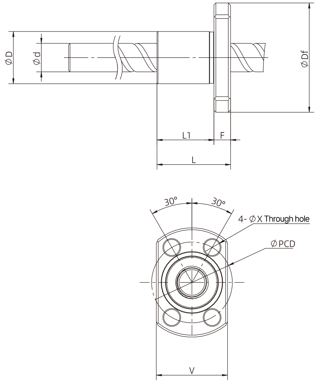
Use this page to review Type 2 mechanical dimensions, drawing references, CAD downloads, and part number construction for flanged single nut configurations.

FBG | FBR Flanged Single Nut - Type 2 Overview
Flanged Mounting
Integrated flange geometry supports direct mounting into compact linear motion assemblies.
Ground Option
FBG indicates a ground ball screw nut option for higher precision requirements.
Rolled Option
FBR indicates a rolled ball screw nut option for cost-conscious motion systems.
Type 2 Geometry
Type 2 configurations support a broader range of compact flange and mounting dimensions.
Mechanical Dimensions
Use this table to compare screw diameter, lead, nut dimensions, mounting dimensions, and load ratings for FBG | FBR flanged single nut - type 2 configurations.
Swipe left or right to view the full dimension table.
| Nut Type |
Screw Diameter D (mm / inch) |
Lead (mm / inch) |
Nut Diameter D (mm / inch) |
Nut Overall Length L (mm / inch) |
Mounting Length L1 (mm / inch) |
Flange Diameter Df (mm / inch) |
Flange Thickness F (mm / inch) |
Mounting Hole Diameter X (mm / inch) |
Bolt Circle Diameter PCD (mm / inch) |
Nut Flat Width V (mm / inch) |
Basic Dynamic Load Rating Ca (N) | Basic Static Load Rating Coa (N) |
|---|---|---|---|---|---|---|---|---|---|---|---|---|
| 2 | 4 (0.16) | 1 (0.04) | 9 (0.354) | 13 (0.511) | 10 (0.394) | 19 (0.748) | 3 (0.118) | 2.9 (0.114) | 14 (0.551) | 13 (0.512) | 560 | 790 |
| 2 | 4 (0.16) | 1 (0.04) | 10 (0.394) | 12 (0.472) | 9 (0.354) | 20 (0.787) | 3 (0.118) | 2.9 (0.114) | 15 (0.591) | 14 (0.551) | 560 | 790 |
| 2 | 4 (0.16) | 2 (0.08) | 11 (0.433) | 19 (0.748) | 15 (0.591) | 23 (0.906) | 4 (0.157) | 3.4 (0.134) | 17 (0.669) | 15 (0.591) | 420 | 570 |
| 2 | 6 (0.24) | 1 (0.04) | 11 (0.433) | 15.5 (0.610) | 12 (0.472) | 23 (0.906) | 3.5 (0.138) | 3.4 (0.134) | 17 (0.669) | 15 (0.591) | 680 | 1200 |
| 2 | 6 (0.24) | 1 (0.04) | 12 (0.472) | 15 (0.591) | 11.5 (0.453) | 24 (0.945) | 3.5 (0.138) | 3.4 (0.134) | 18 (0.709) | 16 (0.63) | 680 | 1200 |
| 2 | 6 (0.24) | 1 (0.04) | 12 (0.472) | 15 (0.591) | 11.5 (0.453) | 24.5 (0.965) | 3.5 (0.138) | 3.4 (0.134) | 20 (0.787) | 16 (0.63) | 680 | 1200 |
| 2 | 6 (0.24) | 2 (0.08) | 15 (0.591) | 17 (0.669) | 13 (0.512) | 29 (1.142) | 4 (0.157) | 3.4 (0.134) | 22 (0.866) | 19 (0.748) | 880 | 1500 |
| 2 | 6 (0.24) | 2 (0.08) | 12 (0.472) | 16 (0.63) | 12.5 (0.492) | 24 (0.945) | 3.5 (0.138) | 3.4 (0.134) | 18 (0.709) | 16 (0.63) | 880 | 1500 |
| 2 | 6 (0.24) | 2 (0.08) | 15 (0.591) | 17 (0.669) | 13 (0.512) | 29 (1.142) | 4 (0.157) | 3.4 (0.134) | 23 (0.906) | 19 (0.748) | 880 | 1500 |
| 2 | 6 (0.24) | 6 (0.24) | 12 (0.472) | 22 (0.866) | 18 (0.709) | 24 (0.945) | 4 (0.157) | 3.4 (0.134) | 18 (0.709) | 16 (0.63) | 870 | 1450 |
| 2 | 8 (0.31) | 1 (0.04) | 13 (0.511) | 16 (0.63) | 12 (0.472) | 26 (1.024) | 4 (0.157) | 3.4 (0.134) | 20 (0.787) | 17 (0.669) | 780 | 1650 |
| 2 | 8 (0.31) | 1 (0.04) | 14 (0.551) | 16 (0.63) | 12 (0.472) | 27 (1.063) | 4 (0.157) | 3.4 (0.134) | 21 (0.827) | 18 (0.709) | 780 | 1650 |
| 2 | 8 (0.31) | 2 (0.08) | 15 (0.591) | 18 (0.709) | 14 (0.551) | 28 (1.102) | 4 (0.157) | 3.4 (0.134) | 22 (0.866) | 19 (0.748) | 1300 | 2300 |
| 2 | 8 (0.31) | 2 (0.08) | 14 (0.551) | 16 (0.63) | 12 (0.472) | 27 (1.063) | 4 (0.157) | 3.4 (0.134) | 21 (0.827) | 18 (0.709) | 1300 | 2300 |
| 2 | 8 (0.31) | 5 (0.2) | 18 (0.709) | 28 (1.102) | 24 (0.945) | 31 (1.22) | 4 (0.157) | 3.4 (0.134) | 25 (0.984) | 20 (0.787) | 1850 | 3000 |
| 2 | 10 (0.394) | 2 (0.08) | 17 (0.669) | 19 (0.748) | 14 (0.551) | 33 (1.299) | 5 (0.197) | 4.5 (0.177) | 26 (1.024) | 22 (0.866) | 1450 | 3000 |
| 2 | 10 (0.394) | 2 (0.08) | 18 (0.709) | 28 (1.102) | 23 (0.906) | 34.5 (1.358) | 5 (0.197) | 4.5 (0.177) | 27 (1.063) | 22 (0.866) | 1450 | 3000 |
| 2 | 12 (0.47) | 2 (0.08) | 19 (0.748) | 19 (0.748) | 14 (0.551) | 36 (1.417) | 5 (0.197) | 4.5 (0.177) | 28 (1.102) | 23 (0.906) | 1600 | 3700 |
| 2 | 12 (0.47) | 2 (0.08) | 20 (0.787) | 28 (1.102) | 23 (0.906) | 37 (1.457) | 5 (0.197) | 4.5 (0.177) | 29 (1.142) | 24 (0.945) | 1600 | 3700 |
Mechanical Drawing
Click the preview image to expand the mechanical drawing. Use the drawing callouts with the dimension table above.
Selection Notes
Screw Diameter
Review screw diameter and lead together to match the required speed, thrust, and positioning needs.
Mounting Envelope
Confirm the nut body, mounting, and envelope dimensions against your mechanical design.
Load Ratings
Compare Ca and Coa ratings during early sizing and confirm final selection with application conditions.
Engineering Review
DINGS’ Motion USA can help review accuracy grade, axial clearance, length, lead, and customization needs.
Downloads
Product Catalogs
FBG | FBR CAD Files
Part Number Construction
| FBG | 06 | 01 | D | X | - | 60 | R | 90 | C3 | Z | - | 001 |
| ① | ② | ③ | ④ | ⑤ | ⑥ | ⑦ | ⑧ | ⑨ | ⑩ | ⑪ |
FBR = Flanged single nut (rolled)
01K = Non-standard ball lead, 1 mm
S = End deflector type
T = Return tube type
C = End-cap type
L = Left-hand
LR = Right- and left-hand
C5 = JIS C5
C7 = JIS C7
C10 = JIS C10
T = ≤ 0.005 mm
S = ≤ 0.02 mm
N = ≤ 0.05 mm
Build a Ball Screw Nut Part Number
Use the ball screw nut part number configurator to help define series, screw diameter, lead, thread direction, accuracy grade, axial clearance, and custom requirements.
Open Part Number BuilderNeed help selecting FBG | FBR flanged single nut - type 2?
DINGS’ Motion USA can help review ball screw diameter, lead, nut style, accuracy grade, axial clearance, load rating, and custom shaft requirements for your application.