
For rotary motion: slotless brushless DC motors
DINGS’ slotless brushless DC motors provide compact rotary motion for applications where a small motor envelope, responsive speed control and smooth operation matter.
Start by defining the required continuous and peak torque at the output shaft, operating speed, supply voltage and available diameter and length.
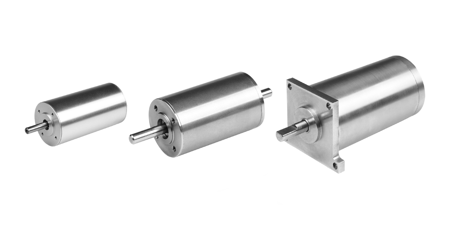
If the motor cannot deliver the required torque directly, a gearbox may help, but it also changes output speed, overall length and reflected inertia. Position control may require encoder feedback.
Size the complete motor assembly, including those components, against the space available in the machine.
For linear motion: coreless push rod actuators
When the output needs to push or pull, a DINGS’ coreless push rod actuator combines a compact brushless motor, reduction mechanism and screw-driven linear output in a single assembly.
The cataloged family covers motor diameters from 8 to 22 mm and rated thrust from 25 to 750 N.

Choose a configuration using the force required throughout the stroke, travel speed, stroke length and duty cycle.
Lead screw and ball screw options offer different force, speed, efficiency and backdriving characteristics. The highest thrust rating is rarely enough information to select an actuator on its own.
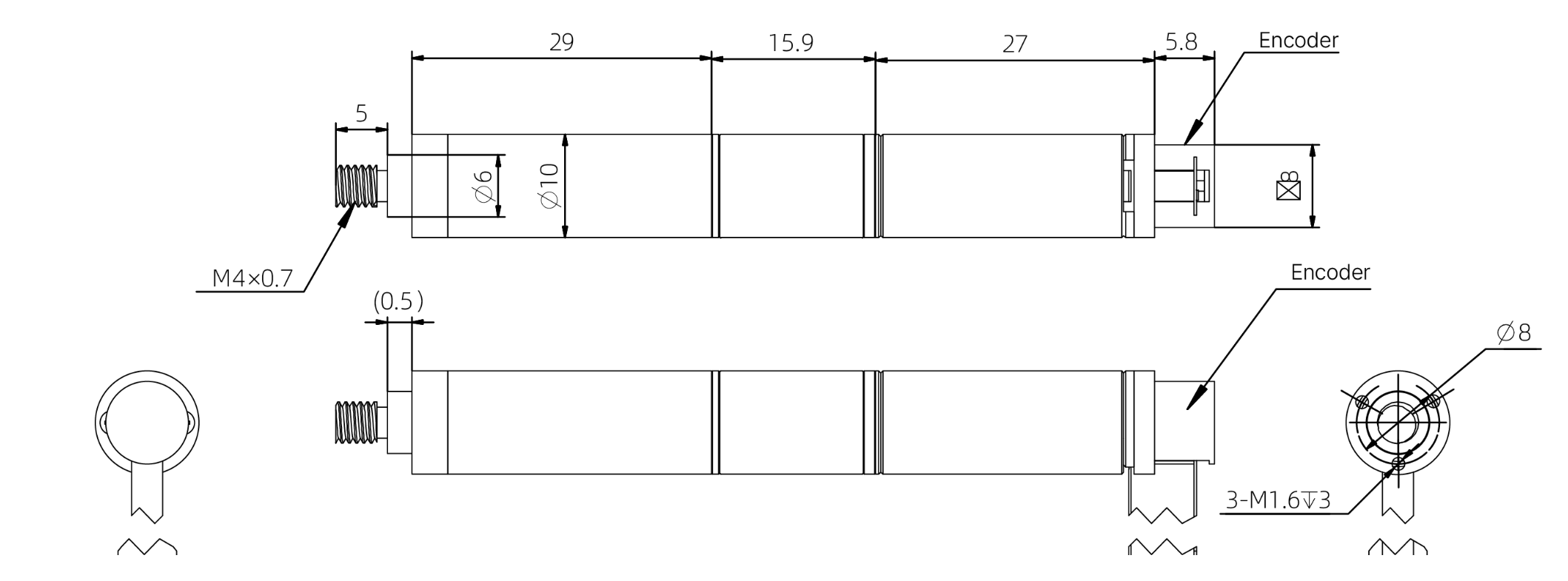
Dimensional drawings help verify the complete actuator envelope, mounting interface and feedback configuration before integration.
Which product fits the axis?
| Output requirement | Starting point | Check before selection |
|---|---|---|
| Controlled rotary motion | Slotless brushless DC motor | Torque at operating speed, duty cycle, feedback needs and space for any gearbox |
| Compact linear push or pull | Coreless push rod actuator | Thrust at the required speed, stroke, duty cycle and screw configuration |
For example, a compact rotary joint and a finger driven by a linear linkage may have similar space limits but need different solutions. The joint calls for a rotary torque calculation; the finger actuator calls for a force and stroke calculation.
Start at the load, not the motor. Selecting from the load at the output helps avoid finding a motor that fits, then discovering the complete mechanism does not.