Precision and Design Features
1. Lead Accuracy of Ball Screws
The lead accuracy of a ball screw refers to the representative deviation and variation of the travel error relative to the effective nut travel or the effective threaded length of the screw shaft. It also includes the variation measured over any 300 mm length of the effective thread and over one revolution (2π rad).

Nominal Travel (l₀) The axial travel for any number of revolutions based on the nominal lead.
Standard Lead (Phs) The lead with corrections applied to account for predicted deformations due to temperature rise and load application.
Target Value of Representative Travel (c) The target value obtained by presetting the standard travel with a positive or negative offset.
Standard Travel (lₛ) The travel for any number of revolutions based on the standard lead.
Actual Travel (lₐ) The actual axial displacement of the nut relative to an arbitrary rotation angle of the screw shaft.
Representative Travel (lₘ) A straight line representing the trend of the actual travel, determined from the actual travel curve using the least-squares method or a similar approximation.
Representative Travel Error (eₚ) The difference between the representative travel and the standard travel corresponding to the effective travel or effective threaded length.
Variation (Vᵤ) The maximum amplitude of the actual travel distance between two parallel lines representing the representative travel.
Variation over 300 mm (V₃₀₀) The maximum amplitude of the actual travel over any 300 mm of the effective threaded section.
Variation over One Revolution (V₂π) The maximum amplitude of the actual travel over one revolution (2π rad) of the effective threaded section.
Allowable Representative Travel Error (±eₚ) and Variation (Vᵤ)
On smaller screens, swipe horizontally to view the full table.
| Effective Thread Length (mm) |
Range | C3 | C5 | |||
|---|---|---|---|---|---|---|
| Over | Up to | ±ep | Vu | ±ep | Vu | |
| - | 100 | 8 | 8 | 18 | 18 | |
| 100 | 200 | 10 | 8 | 20 | 18 | |
| 200 | 315 | 12 | 8 | 23 | 18 | |
| 315 | 400 | 13 | 10 | 25 | 20 | |
| 400 | 500 | 15 | 10 | 27 | 20 | |
| 500 | 630 | 16 | 12 | 30 | 23 | |
| 630 | 800 | 18 | 13 | 35 | 25 | |
| 800 | 1000 | 21 | 13 | 40 | 27 | |
2. Allowable Deviations for Ball Screw Lead Accuracy
High Precision Grade (C3, C5) – V300 / V2π
| Precision Grade | C3 | C5 | |||
|---|---|---|---|---|---|
| Item | V300 | V2π | V300 | V2π | |
| Permissible Value | 8 | 6 | 18 | 8 | |
Standard Precision Grade (C7, C10) – V300
| Precision Grade | C7 | C10 |
|---|---|---|
| V300 | 52 | 210 |
The representative travel error (eₚ) for C7 and C10 is calculated using the following formula:
lu = Effective thread length (mm)
3. Material, Heat Treatment and Hardness
The standard material, heat treatment, and hardness of DINGS' ball screws are shown in the table below. Values may vary slightly depending on the series and model.
| Component | Material | Heat Treatment | Thread Surface Hardness |
|---|---|---|---|
| Screw Shaft | SUJ2 (JIS G 4105) | Induction hardening | HRC 58–62 |
| Screw Shaft | S55C (JIS G 4105) | Induction hardening | HRC ≥58 |
| Screw Shaft | SUS440C | Quenched and tempered | HRC ≥55 |
| Ball Nut | SCM420H (JIS G 4105) | Carburized and hardened | HRC 58–62 |
| Ball Nut | SUS440C | Quenched and tempered | HRC ≥55 |
Note: S55C material is used for rolled ball screws, while SUJ2 material is used for ground ball screws.
4. Axial Clearance and Preload
Axial Clearance
In general, a standard single-nut ball screw has a small axial clearance between the screw shaft and the nut.
When an axial load is applied, the sum of this axial clearance and the elastic displacement caused by the load increases the clearance, resulting in backlash.
To eliminate such backlash, the axial clearance of the ball screw must be made negative by applying elastic deformation in advance between the screw shaft and the nut. This method is referred to as preload.
The combinations of axial clearance and accuracy grades for DINGS' ball screws are shown in the table below.
| Accuracy Grade | Axial Clearance | |||
|---|---|---|---|---|
| Z (Preload) | T (≤0.005 mm) | S (≤0.02 mm) | N (≤0.05 mm) | |
| C3 | ● | ● | ● | ● |
| C5 | ● | ● | ● | |
| C7 | ● | ● | ||
| C10 | ● | ● | ||
Effect of Preload
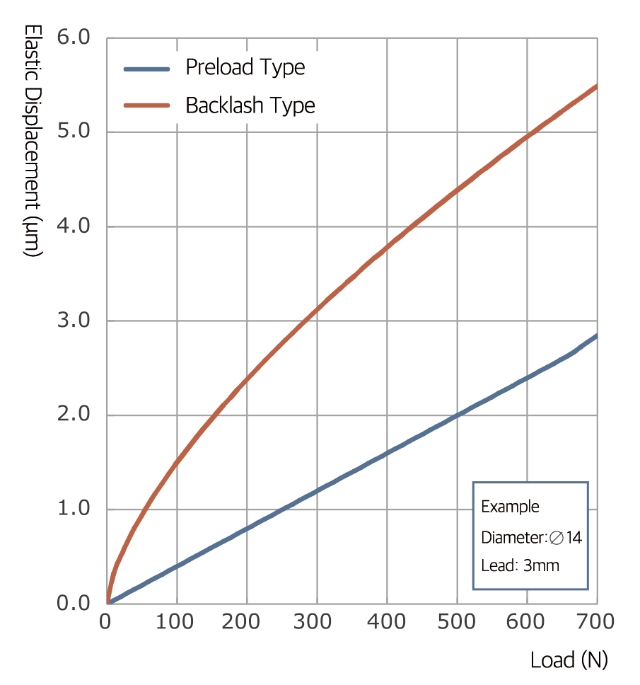
Applying preload not only eliminates axial clearance in ball screws, but also reduces axial displacement caused by axial loads, thereby increasing stiffness.
The figure below illustrates the difference in elastic displacement under axial load between a clearance-type ball screw and a preloaded zero-clearance ball screw.
Appropriate Preload Amount
The preload amount should be determined based on the required stiffness or allowable backlash. However, applying preload may result in:
- Increased dynamic torque
- Reduced positioning accuracy due to heat generation and temperature rise
- Shortened service life
For that reason, preload should be set as low as possible while still meeting performance requirements.
Preload Methods
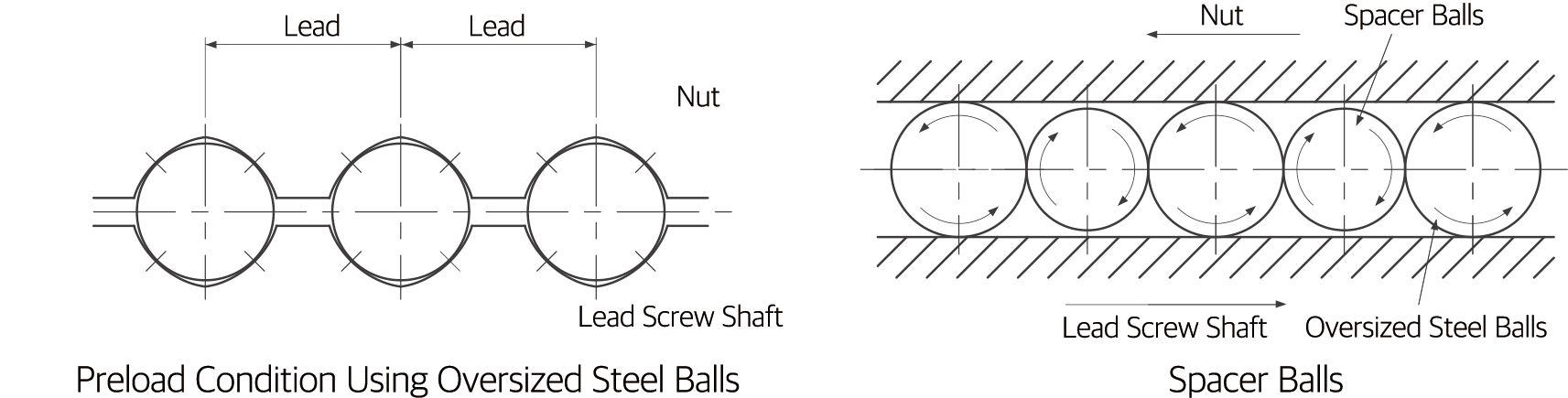
Ball screws are generally preloaded using the double-nut preload method, in which spacers are inserted between two nuts. DINGS' ball screws also use a large-ball preload method, where steel balls slightly larger than the clearance between the screw shaft and the nut are inserted.
This method eliminates clearance using only a single nut while maintaining a compact structure. Spacer balls slightly smaller than the preload balls are alternately used to help prevent deterioration of motion performance.
Preload Management
Direct measurement and control of ball screw preload are difficult. Therefore, preload is typically managed by converting it to preload running torque and controlling it through torque measurement.
To ensure proper preload, running torque is measured under defined conditions. Differences in lubrication and operating conditions may cause variations in measured torque. Starting torque is slightly higher than running torque.
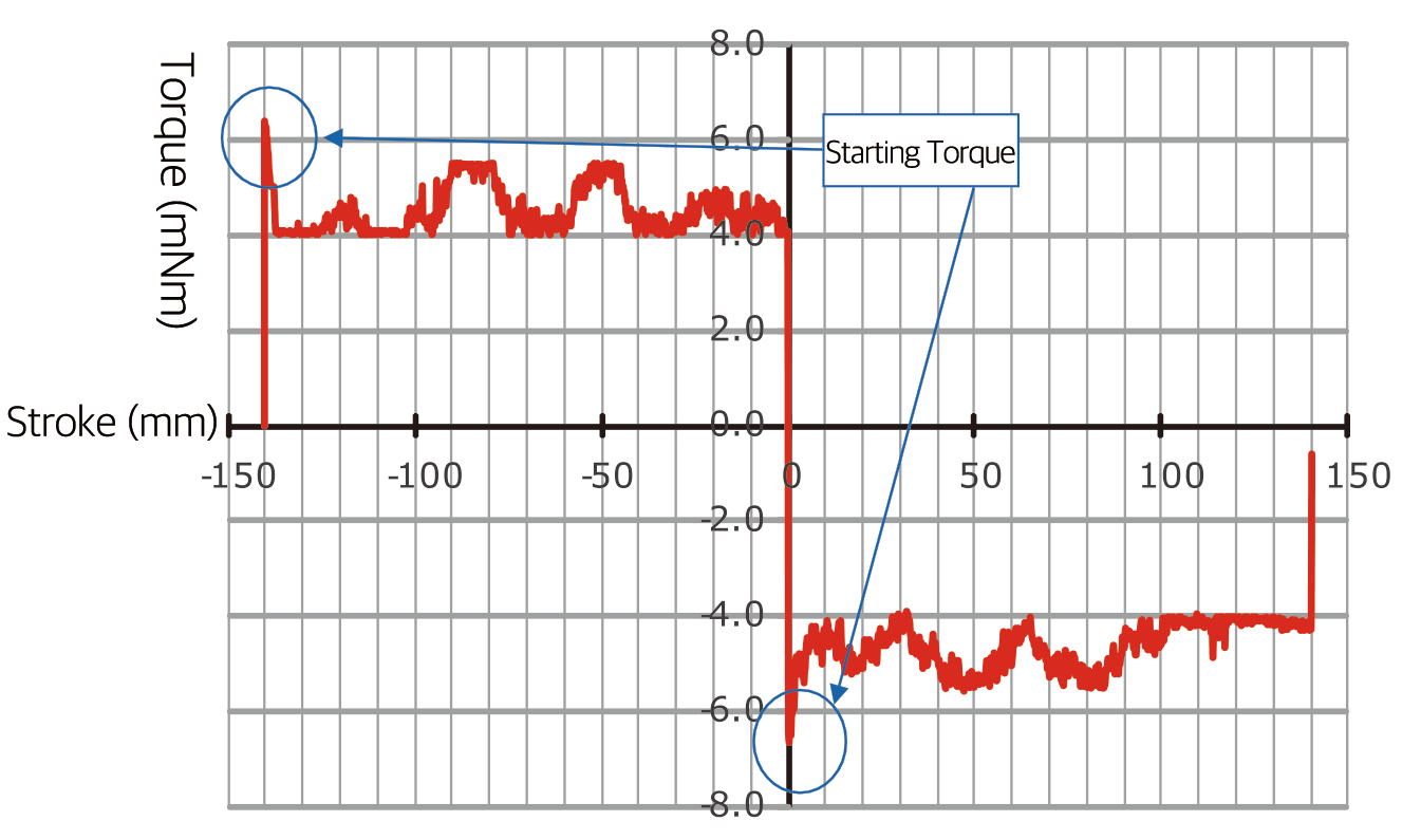
Note: The torque variation illustrated is intentionally exaggerated for explanatory purposes.
5. Rust Prevention and Lubrication
Rust Prevention
DINGS' ball screws are coated with rust-preventive oil for long-term storage. Before use, remove the oil with clean refined kerosene and apply lubricating oil or grease. Grease can be applied prior to shipment upon request, although long-term storage with grease may cause rust.
Note: The rust-preventive oil is for corrosion protection only and provides no lubrication. Using the ball screw without removing this oil may reduce service life and cause increased torque or abnormal heat generation.
Lubrication
Lubrication is essential when using ball screws. Insufficient lubrication may cause increased torque and shortened service life. Proper lubrication helps suppress temperature rise due to friction, efficiency loss, and accuracy degradation caused by wear.
- Grease lubrication: Lithium soap-based grease is generally recommended.
- Oil lubrication: ISO VG 32–68 turbine oil is recommended.
Selecting the appropriate lubricant for the application is especially important. For miniature ball screws, grease churning resistance may increase torque.
- MSG No.1 (NLGI No.1): For low-speed positioning applications requiring smooth motion
- MSG No.2 (NLGI No.2): For high-speed and general-purpose applications
Recommended Lubricants
| Lubricant Type | Category | Product Name |
|---|---|---|
| Grease | Lithium-based Grease | AFG Grease |
| Lubricating Oil | Slideway oil or turbine oil | Super Multi 68 |
Inspection and Replenishment
When using grease lubrication, inspections should be conducted every 2–3 months. When using oil lubrication, inspections should be conducted weekly. During inspection, check lubricant quantity and contamination, and replenish as necessary.
| Lubrication Method | Inspection Interval | Inspection Items | Replenishment / Replacement Interval |
|---|---|---|---|
| Automatic Intermittent Lubrication | Weekly | Oil quantity, contamination | Replenish appropriately at each inspection based on reservoir capacity |
| Grease | Initial operation: 2–3 months | Contamination, chips, foreign matter | Typically replenished once per year; adjust based on inspection results and remove discolored old grease |
| Oil Bath | Before daily operation | Oil level | Adjust appropriately according to consumption |
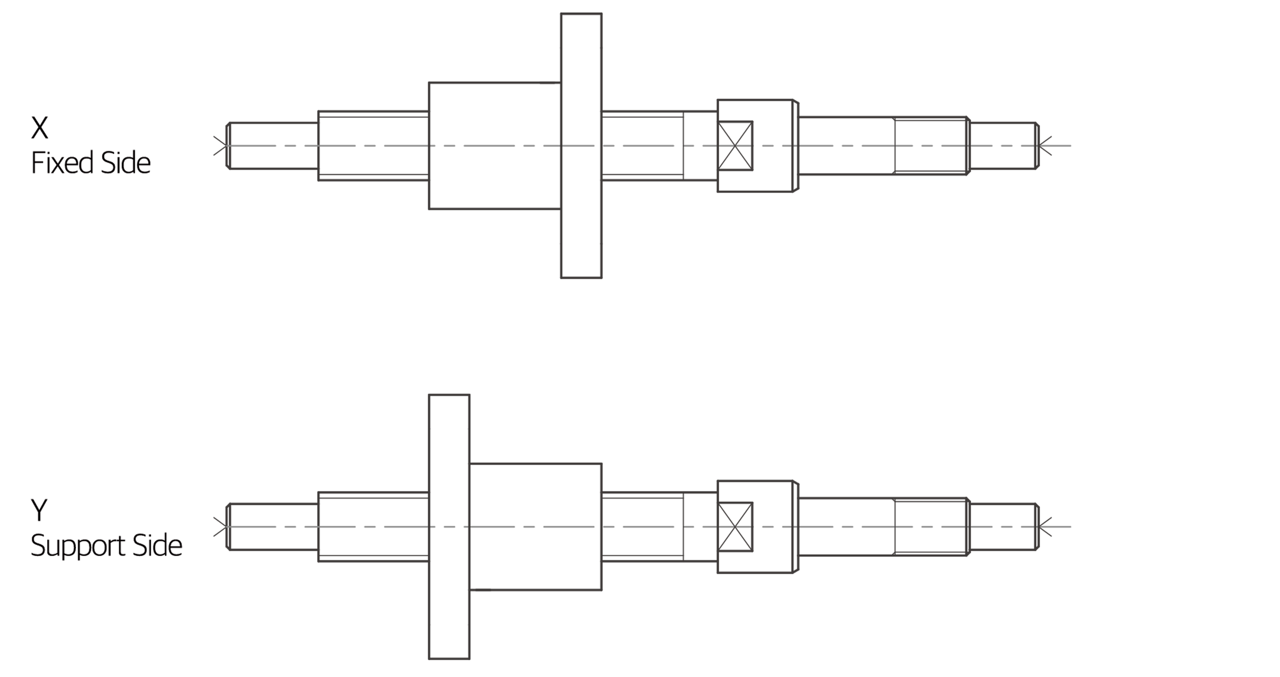
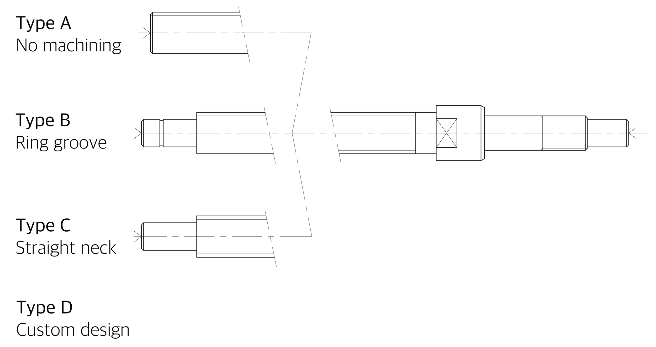
6. Support-side Shaft End Machining Type
7. Nut Flange Orientation