
How Absolute Encoders Work in Frameless Motors—and What You Need to Know to Integrate Them
When precision matters, knowing the exact position of a motor’s rotor at every moment is essential. That’s why in many applications using frameless motors—especially in robotics, medical devices, or aerospace—designers are moving beyond hall sensors and turning to absolute encoders.
But integrating absolute encoders into frameless motors isn’t always straightforward. In this post, we’ll break down how these encoders work, the specific design considerations to keep in mind, and what mistakes to avoid when incorporating them into your next project.
Why Use an Absolute Encoder with a Frameless Motor?
In frameless motor applications, the motor stator and rotor are integrated directly into the host machine’s structure, offering compact size, high torque-to-weight ratio, and design flexibility. However, this flexibility means there's no standard housing to conveniently mount a feedback device.
Depending on your application:
Speed-only feedback? Hall sensors may suffice.
Precise positioning? You’ll likely need an absolute encoder.
Absolute encoders provide a unique digital output for every position of the rotor, meaning the motor knows exactly where it is—even after a power cycle.
How Frameless Motor Encoders Work
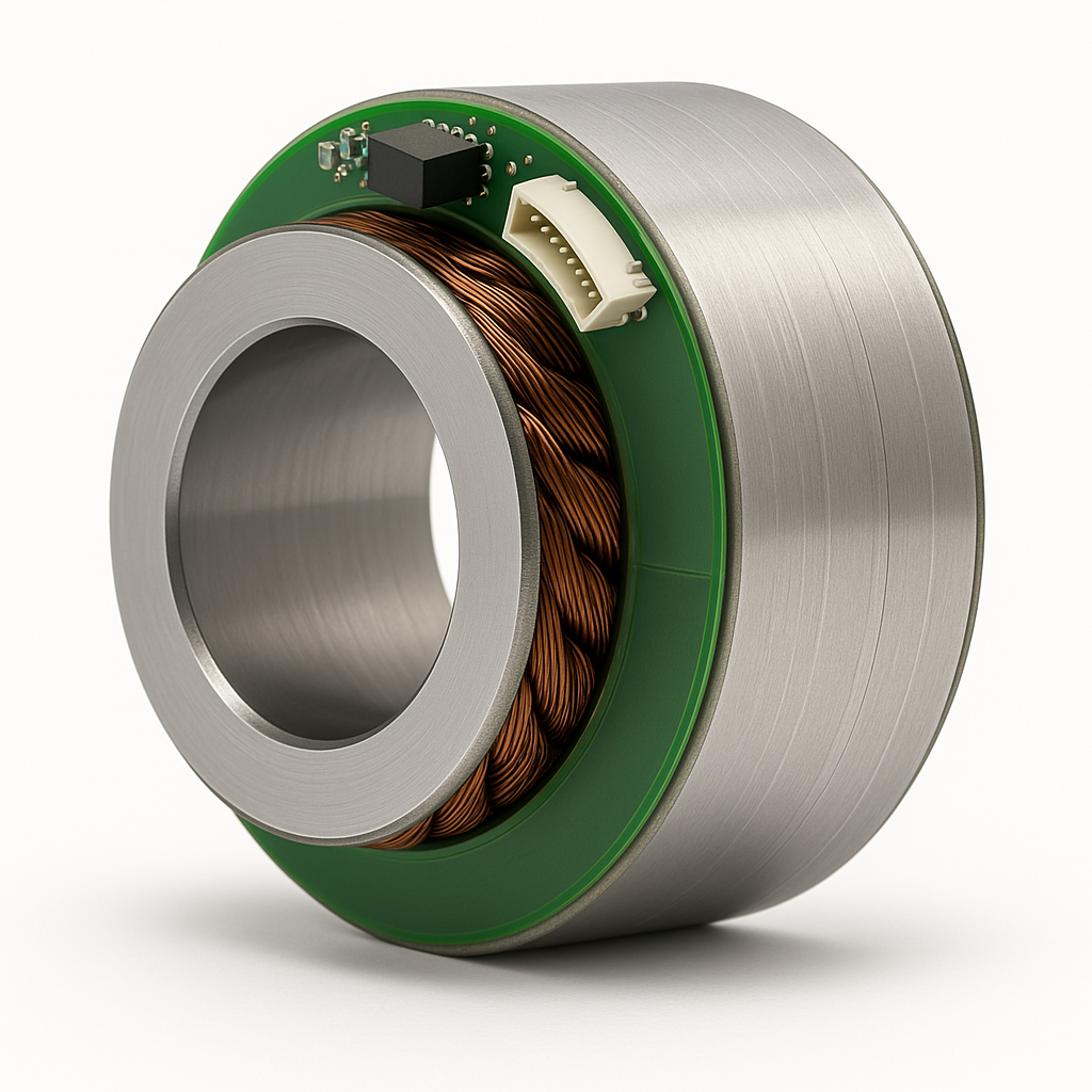
Absolute encoders used in frameless motors operate using a contactless magnetic principle.
A magnetized rotor—typically a Neodymium cylinder—is fixed to the rotating portion of the motor.
A magnetic sensor is integrated onto the stator’s PCB, offset slightly from the magnet’s center.
As the rotor turns, the magnetic field rotates, and the sensor detects the angular position based on the changing field direction.
This configuration enables high-resolution angle detection without physical contact or wear components. Depending on the application, either end-of-shaft or side-shaft mounting methods can be used, with tradeoffs in linearity and mounting complexity.
Integration Considerations for Design Engineers
To successfully integrate an absolute encoder into a frameless motor application, several factors must be carefully managed:
Rotor-to-Sensor Distance
The sensor must sit within the active magnetic field. For instance, in compact motors like the RMD Series, the magnet typically needs to sit a few millimeters above the sensor. If the distance is too great or too small, the signal strength can be affected, leading to reduced accuracy or missed signals.
Mounting Alignment
Precise alignment between the rotor magnet and the stator sensor is essential. Off-axis configurations introduce challenges with field uniformity, and even slight misalignments can introduce errors. Tools like bias current trimming (available on some sensors) can help linearize output when dealing with off-center fields.
Sensor Orientation
The angular measurement is based on the in-plane component of the magnetic field. Designers must consider the sensor’s sensitive axis and the magnet’s orientation to ensure reliable performance.
Sensor Calibration & Interface Options
Modern magnetic angle sensors used in frameless motor applications often come with a wide range of configurable outputs and communication protocols. These may include:
SPI or SSI interfaces for serial digital angle readouts
ABZ quadrature output for incremental encoder functionality
PWM output with a duty cycle corresponding to angular position
Some sensors also offer programmable features such as:
Zero position setting for installation calibration
Rotation direction adjustment
Magnetic field diagnostic thresholds for alignment verification
Digital filtering settings to balance response time and resolution
These configuration options allow designers to fine-tune encoder behavior to match the needs of their control system, from low-latency servo loops to high-resolution positioning applications.
Common Mistakes to Avoid
Inadequate rotor extension: If the rotor magnet is too low, the encoder won’t detect rotation.
Improper magnet selection: The wrong magnet type or field strength can lead to inconsistent readings.
Overlooking filtering settings: In high-speed control loops, improper digital filtering can destabilize the system.
A Note on Frameless Motor Customization
At DINGS’ Motion USA, we work with OEMs to integrate frameless motors with encoder solutions tailored to your form factor, feedback requirements, and performance goals. From field-tested mounting clearances to feedback interface options, we’ve seen the small details make a big difference.
Interested in a Frameless Solution?
We’re here to help you select and integrate the right encoder-equipped frameless motor for your next high-performance application. Reach out to our team to start the conversation.